A Fiber Optic Connector Primer
By Steve Somers, Vice President of Engineering
Optical fiber transmission of AV signals has come of age and it's time to take another step along this new, adventurous road. A fiber solution may sound like a great idea for those challenging long-haul or highly secure applications, and then reality sets in. The fiber transmission solution is still a serious investment consideration requiring careful planning and implementation. Which equipment transmission format should be used: analog or digital? Is digital transmission hardware available? Does this application require multimode or singlemode fiber? How do I deal with the customer's existing installed fiber? What fiber connectors do I use?
In the last issue of Technically Speaking, I presented the basic characteristics and considerations for the fiber conductor. In this issue, we will look at the Subscriber Connector - SC, Straight Tip- ST, Fixed Connection - FC, and Lucent - LC fiber connectors, their application, performance, and their termination requirements. Unlike the steadfast, ubiquitous BNC connector used for copper coaxial wiring in AV, fiber connectors are evolving with the maturity of fiber technology. Whereas copper connections rarely have a significant signal loss impact in AV applications, fiber connections do have measurable impact at each interface point within a distribution system.
Ultimately, questions about the physical connection must be answered. Perhaps the fiber transmission equipment itself will dictate connectivity. In other cases, the choice of connectivity for most or all of the fiber distribution may rest with you. Although fiber cable losses do escalate depending on the type and quality of fiber installed, each connection point imparts a definitive loss. Depending on choices made, cumulative connector interface signal losses could exceed the loss realized in the fiber cable itself!
Keeping a Loss Budget
Optical power, like electrical power, is commonly measured in dB with -3 dB, relative to the source's reference level, representing the half-power point. For copper circuits, digital or analog, the loss budget for connectors is typically assumed to be “zero” for all practical purposes. In other words, the ohmic loss due to connector contact resistance is usually negligible compared to the overall cable loss. Just the opposite may be true in most fiber installations. For fiber cabling in AV applications under about 1,000 feet, the cable loss may be easily less than 3 dB. In fact, increased light dispersion, another form of loss discussed in my previous article, usually overshadows fundamental attenuation loss. For multi-kilometer-realm distributions, multimode fiber dispersion can become significant, whereupon the use of lower loss singlemode fiber may be dictated.
In either case, each connector interface encountered by the distributed signal has a measurable loss associated with it. Often, the largest initial loss occurs at the output coupling of the source followed by the first system patch encounter. The idea behind a good fiber connector, of course, is to minimize interface losses between the connected fibers, thus keeping within a loss budget that provides system reliability over long time periods. Connector interface loss is also specified in dB. While the interruption of the light path alone represents a certain signal loss at the interface due to inexact mating of the optical fiber ends, other anomalies such as poor surface condition of the fibers and non-parallel end surface alignment may exist that drastically increase losses beyond the anticipated level.
The escalation of high-speed laser fiber transmission design poses a new concern for the endface design of fiber terminations. Endfaces become highly reflective at very high transmission rates and require special treatment such as angle polishing or spherical polishing to minimize loss effects.
But, to be specific on the connector loss budget, nominal connector interface loss may range from about 0.1 dB to as much as 1.5 dB per connection under expected installation conditions. Considering how many patch connections may be required from the source through an equipment rack patch bay, routers, and the workspace, the loss budget can escalate rapidly. But, what about unexpected conditions?

On Being Nominal
When we interface daily with other people, don't we automatically, or perhaps rhetorically,say: “Hello, how are you?” The obligatory answer from the quizzed: “Oh, I'm fine.”
My answer is always: “I'm nominal.” It's become a kind of trademark for me. Now, people who know me well expect me to say it. Those who don't know me well are taken aback. Nominal? What does that mean? Is it the same as fine? Well, it means all is normal and operating under the average, expected conditions. For me, I guess that means fine, but you wouldn't remember, nor endear, my reply if I simply said “fine”.
For fiber system designs, nominal is fine. What we want is a design that considers the unexpected and still achieves nominal operation. Some would call that “design headroom”. Or, another way to look at it is to plan for the worst and expect better most of the time. I think this is what the designers of fiber connectors have in mind. Fiber connections deal with very small mechanical tolerances with the opportunity for fiber misalignment typically a rule, not an exception.
Reliable connection requires that fiber ends be optically smooth and square. End-to-end positions must align precisely...and, we're talking about a few microns, or millionths of a meter. Remember from my previous discussion on fiber cable that the popular multimode fiber diameters are 50 and 62.5 microns. Singlemode fiber is only 8 to 9 microns in diameter. Contrast these dimensions to the diameter of the typical human hair, which ranges from 17 to 180 microns. Misalignment by “just a hair” can mean disaster.
Tight tolerances like these require interface cleanliness. Note in this article that some photographic figures depict a small boot covering the connector ferrule tip. Fiber connectors and assemblies are commonly shipped with a boot in place for good reason. A fingerprint smudge or extraneous dust and dirt can seriously affect connector performance up to and including transmission failure. Use that protective boot anytime the fiber is not connected!
The Ferrule, Not the Exception
Proper keying for fiber connectors is essential. Within all current fiber connector designs is a component called the “ferrule”. This is the precision feature that ensures alignment during connector mating. The fiber end is captivated within the ferrule by either adhesives or crimping so as to become a permanent component of it. The ferrule end is finished, or polished, after insertion of the embedded fiber to provide the smooth interface required for coupling. The ferrule is often made from a hardened material such as ceramic, but may be stainless steel, plastic, or tungsten carbide. The common ferrule diameters are 2.5 mm - SC, ST, and FC, and 1.25 mm - LC.
Because the ferrule can be manufactured to tight tolerances, it is the primary alignment feature for the fiber. Springloaded receptacles interface the ferrule to provide even, concentric alignment support between the fiber and the LED or laser source as well as for the receiver's photo diode. In addition, fiber cables may be coupled using adapters which incorporate similar spring-loading alignment features.
Connector Cameos
Fiber connectorization is evolving with technology and application. There are perhaps twelve or more types in use today; each of them born from specific needs and/or technology limitations of the time. The trend today is toward rugged, moderate cost, compact connectors able to support the increased density required of newer distribution systems. As you would expect, the telecommunications industry is driving the development, in large part, due to the burgeoning need for fiber connectivity for all types of communications and entertainment services.
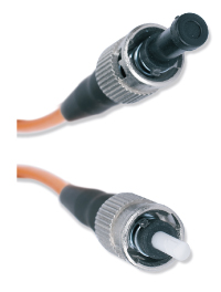
My first experience using fiber began with systems employing the ST connector. See Figure 1. Introduced in the late 80s by AT&T, it is also referred to as a BFOC - Bayonet Fiber Optical Connector. The ST, for “straight tip”, is most popular with multimode LANs and CCTV systems but is only recognized by one fiber connectivity standard. The ST appears to be a miniature BNC connector with a ceramic tip extending past the connector body. In the fiber vernacular it is a simplex bayonet-style twist-lock connector. Handling ST connectors requires special attention to the ferrule since it is unprotected and vulnerable. While still popular in industrial applications, ST connector popularity is waning in favor of other more compact, keyable form factors.
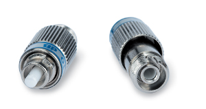
A cousin of the ST connector is the FC Connector. FC stands for “fixed connection” and is most often used for singlemode applications in telecommunications. This style resembles the ST with its keying and metallic construction, but uses threaded screw-on captivation instead of a bayonet locking approach. Geared for high vibration environments, the FC connector is cited in the TIA/EIA-604-04. See Figure 2.
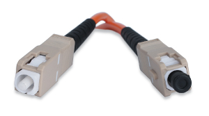
Probably the most popular connector for most of us is the SC connector. SC stands for “Subscriber Connector”. We know it as the prescribed connector within TIA/EIA-568B.3, and it is often referred to as a “premises” connector. See Figure 3. It is a fairly compact hard plastic design first standardized in 1992 by the ISO/IEC. This push-pull connector is available as a simplex or duplex connection assembly and is color-coded to indicate the fiber type: beige for multimode and blue or green for singlemode. Although the SC is widely used for premises installations, it is not the most compact design available. The duplex footprint requires an area of 0.378 square inches...which is significant real estate when building fiber routing gear.
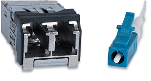
A smaller cousin of the SC connector is the LC connector. See Figure 4. Designed by Lucent Technologies, the LC is the first really durable small form-factor connector intended to increase packing density for fiber equipment systems. The LC, which resembles a smaller version of the SC, increases packaging density by 50% with its narrow footprint and push/pull snap-lock design. This is a significant gain when considering connection density within the Telco switching environment. LC connectors can easily be ganged into a keyed duplex arrangement and feature a locking clip similar to a regular RJ45 connector. LC connectors are gaining popularity due, in large part, to their use in SFF - Small Form Factor optical transmitter/receiver assemblies.
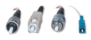
Compare the physical size of these four connectors in the line-up photo that is Figure 5. Clearly, the LC connector is gaining popularity with its low interface loss specs and its small footprint.
What to Look For
Regardless of the connector style, we're looking for alignment accuracy, ruggedness, repeatability, and low loss. Keyed connectors can attain coupling loss repeatability of 0.2 dB typically. Since the connector plays a significant role in transmission losses, there are two primary parameters that once again become important just as they are with copper cabling: insertion loss and return loss.
Insertion loss in this context refers to the decibel loss induced by the connector interface as discussed earlier. Return loss, just as with copper cabling, refers to energy reflected back to the signal source due to endface reflectivity. Specifying connector insertion loss and return loss parameters depend to a degree on the test suite utilized. However, while connector specifications vary from manufacturer to manufacturer, most are conforming minimally to the TIA/EIA 568B.3 commercial data network requirements. TIA/EIA-568B.3 specifies a maximum insertion loss of 0.75 dB for both multimode and singlemode fiber. The return loss is minimally ≥20 dB for multimode and ≥26 dB for singlemode. See Table 1. An SC connector may typically have only about 0.3 dB loss at its interface while a connector like the LC can be as low as 0.1 dB.
So, what does all this mean? The insertion loss is straightforward in that we merely add up all the connector interfaces and multiply by the expected loss in dB per connector. Then, add to that the total cable loss for the run length calculated for the critical upper frequency. The sum of these two sets of losses yields the basic system loss due to transmission line and connector losses.
That's an important number...one that all designers will use to determine if the system will operate “nominally” based on the difference between the source transmitter optical power and the optical receiver's sensitivity. But, that's not the whole story. The return loss parameter tells us how much energy may be reflected back to the source. Reflected energy returns down the cable in the form of a delayed signal. This delayed signal can be regarded much like an additional “mode” discussed in the last article on fiber cable.
Remember that multiple modes, or light paths, occurring in the fiber are interpreted at the receiver as an increase in signal jitter for digital systems and slower rise time for analog systems. In other words, poor return loss performance at each connector junction is a cumulative effect which will degrade receiver decoding even though signal level may be within nominal boundaries. This effect manifests as a degraded zero crossing of the eye pattern for digital signals such that the receiver's ability to track and lock onto data is impaired to the point of performance failure. Comparatively, analog fiber signals exhibit degraded rise time, which appears as a very fuzzy image.
For example, for each connector having a return loss of only 20 dB, about 1% of the signal is reflected. This can become significant depending on the number of connectors within a signal run. A return loss of 26 dB drops that level to about 0.3% and at 50 dB the loss is approximately .001%.
The Extron FOX 500 Fiber Optic Extender Steve Somers has noted in this article that the LC connector offers high performance with low insertion losses in a small form factor, and is gaining popularity in telecommunications applications that require high density fiber optic connections for telco switching.
Following extensive research on the various fiber optic connectors, we have also chosen to use LC-style receptacles for the Extron FOX 500 Fiber Optic Extender for their compact footprint, so that fiber as well as all necessary connections for RGBHV, audio, and RS-232 serial control can easily co-exist on the rear panel. The LC dual receptables also enable easy dual-fiber connectivity for bi-directional box-to-box communications between the FOX 500 transmitter and receiver, enabling full RS-232 pass-through, control from either location, and real-time system monitoring.
Terminating Considerations
Traditionally, fiber termination has been both slow and expensive, and required expensive equipment and technical skill. Those concerns are perhaps well-founded when considering the termination of singlemode cable in the field. However, borrowing an old song lyric: “The times, they are a changing...” In some cases, pre-terminated cables are in order and can be ordered from a variety of sources in any connector style. Most short patch cables fall into this category.
For custom installations, on-site termination may be the only option available. But, there are still options. Field termination of singlemode fiber is performed to a lesser extent now that splicing kits are available, which minimize equipment and required technical skill. Even for multimode cable, new splicing methodologies employ a simple fiber cleaving method followed with assembly of the cable to a pre-finished connector/cable pigtail. In effect, this solution is a simpler fiber-to-fiber butt splice. The splicing regime typically utilizes a special optical gel that facilitates fiber endface coupling.
Alternately, fiber termination may be accomplished with a new system developed by Corning combining a simple cleave and crimp system. The connector ferrule endface is pre-finished with an imbedded fiber. This internal fiber has a pre-cleaved end embedded within a crimp tube that contains an optical gel. The fiber cable to be terminated is stripped and cleaved using an inexpensive preparation tool. The prepared fiber end is inserted into the crimp tube and aligned against the embedded fiber using an optical device that allows the technician to gauge the alignment easily. Upon alignment, the connector is crimped and the termination completed. The total time required is about two or three minutes.
Multimode cable terminations usually consist of two types of endface polishes: the flat-face air gap type and the contact type. Of the two, the simple flat air gap style may incur a return loss of ≥14 dB which corresponds to about 3.2 percent light reflection back to the source. The contact type is preferred since its return loss is ≥20 dB, or only one percent.
There are five typical singlemode cable factory termination endface polish methods for controlling insertion loss and return loss: flat, Physical Contact - PC, Super Physical Contact - SPC, Ultra Physical Contact - UPC, and Angled Physical Contact - APC. Each of the physical contact methods from PC on through UPC employ varying degrees of endface precision and yield progressively lower coupling loss and better return loss. The APC style provides ≥65 dB return loss which keeps reflections down to 0.000032%. While singlemode APC connections offer the best performance, the angled polish surface requires that all connector interfaces possess a precision keying feature. Because of the precision required, most singlemode connections are factory made. Field termination is best accomplished using pre-finished pigtails that may be butt-spliced.
Terminating Discussions
Knowing when to terminate this discussion is perhaps just as important as selecting the right fiber connector and properly terminating it. We've covered some basics on fiber connectors that will hopefully serve you well as you encounter their application. In addition, the same parameters apply to other connector styles that I did not have time to address. Careful attention paid to connector selection and fiber termination provides the best performance available for any connector technology of your choice. After all, the idea is to design systems that attain nominal operation which leads to high system reliability.