HD-SDI: More Possibilities than Just Television
By Steve Somers, Vice President of Engineering
It seems that the popular concept of digital video among the masses arrived with the DVI connection to the computer monitor. Of course, the DV format for consumer video cameras arrived earlier, but for most it just didn't seem like digital video. Why? I think we've only recognized what digital video can be since the moment we could really interact with it, or touch it so to speak…the moment that we realized a crisp, pronounced benefit in our daily life…the moment it simplified what used to be complex or annoying…and, unforgettably, the moment it failed to perform.
And, that's the way it is with anything digital. When it's working, it's very, very good; when it stops working, we're lost. There's only one way to describe the non-working situation: "It's broke." But, belaboring the challenges is not why we're here. The road of progress is paved with resolve and vanquished challenges. Experience guides each of us along that road.
Experience tells us to consider alternatives; to research other successful solutions to technical challenges. Such is the case here. The television industry has used the high definition serial digital interface, or HD‑SDI, for about 10 years now to trundle full bandwidth, uncompressed HD video from point A to point B within the television production environment. Lower cost HD cameras and video production equipment bring HD‑SDI into the fore as an essential interface to understand and exploit. Recent additions to the cadre of the SMPTE1) serial digital standards are now positioning HD‑SDI as a competitive, high performance interface for RGB graphics in addition to its role in television. HD‑SDI debuted as an open, robust gigabit-plus transmission scheme long before digital interfaces such as DVI became available.
Establishing a Reference Point
Why compare HD-SDI to DVI? With the DVI having more press and wide use, it's important to establish a point of reference right here before moving on. RGB 8‑bit image data (via 10‑bit symbols) is transferred over the DVI using three digital data lines and one clock line. That's four parallel differential line pairs not including display communications and control. Each of the three video data pairs operates at a rate of 1.65 Gbps when used at maximum resolution. Multiply by three and the DVI bit rate for RGB support is 4.95 Gbps. The clock rate is variable from 25 to 165 MHz depending on the resolution desired. So, DVI has quite a lot of rate flexibility, but is challenging to distribute with its multiple data line pairs and interface control requirements.
One HD-SDI feed operates at 1.485 Gbps over low-loss RG6-style video grade coaxial cable. High definition video is transferred at 10 bits per symbol in the Y, U, V domain. That's another designation for component video, which provides a quality level of lossless compression. All digital television signals, including high definition rates up to 1920 x 1080 at 30 frames interlaced, are managed successfully over the HD‑SDI. The component format allows transmission of HD because the luminance (Y channel) is the only full bandwidth channel. The U and V channels representing chroma are transmitted at one-half bandwidth; an acceptable tradeoff based on our understanding of the human visual system. A variety of data may be accommodated on the HD‑SDI as long as it is packetized to operate within the HD‑SDI's fixed clocking rate. But, as you will see, HD‑SDI has its variants which can transmit full-bandwidth, 10‑bit RGB and an alpha channel to boot. What's an alpha channel? Read on.
HD-SDI Inside
ATSC standard definition and high definition rates are ultimately compressed using MPEG‑2 in order to fit them within the bandwidth limits of one television channel. At the point of creation, HD video is routed within the production environment uncompressed via HD‑SDI at the 1.485 Gbps rate. After compression, the high definition video rate plummets to 19.4 Mbps (about 77:1). As a compressed video transport means, HD‑SDI can deliver a data payload of three standard definition SDI signals, or about 50 MPEG‑2 compressed HD feeds, or as many as 250 compressed standard definition signal feeds.
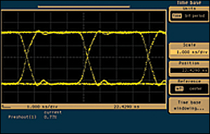
Figure 1 shows the electrical presentation of the HD‑SDI video signal captured at the source. The number of bit transitions creates the illusion that the signal appears to be crossing the zero axis at each bit position creating a display called an "eye pattern". The "eye" refers to the opening between the maxima and minima between each bit cell transition. In this presentation, the eye pattern illustrates a clean, open, strong source signal. Normal signal level is 0.800 volt peak-to-peak. The rise and fall times are nominally 270 picoseconds. Eye pattern quality is one measure for successful data transmission.
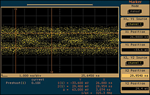
As the signal propagates through a coaxial cable, transition times lengthen just as they do with an analog signal. Slowing signal transitions and cable attenuation cause amplitude decrease, which results in the eye closing down. See Figure 2. This condition challenges receivers to recover the clock signal and data transitions. When the amplitude and rise/fall time drops to a level insufficient for the receiver to equalize frequency response and recognize transitions, the system loses synchronization. The result is the well-known "cliff effect".
HD-SDI employs a signal coding method called NRZI, Non-Return to Zero Inverted. NRZI is a coding method that facilitates recovery of the clock from the actual data transmission. NRZI coding minimizes residual DC component on the signal as well. Due to the construction of this coding scheme, the bit rate is equivalent to the frequency component in MHz. In other words, 1.485 Gbps is equal to 1.485 Gigahertz.
In the digital component realm, there is no need to dedicate equivalent time for signal sync pulses that the analog domain necessitates. Digital transmission makes use of the sync and blanking time for sync and a host of other signals. To synchronize a digital television signal, the receiver need only recognize a single code word representing the end of the active video and another code word for the beginning of active video on the next line. The EAV and SAV codes perform this function. The balance of the blanking time interval may be used for other information like control, timing, and audio information.
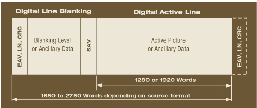
The data organization during one horizontal line is shown in Figure 3. SMPTE 274M defines several resolutions for high definition digital video. Each sample during one line is 10 bits wide. During active video, there may be 1280 words (for 1280x720 format) or 1920 words (for 1920x1080 format). The total number of words per horizontal line time ranges from 1650 to 2750 words depending on the specific format used within SMPTE 274M. For the common 1920x1080 format, the total word count is 2200. Data carried during the blanking interval is bounded by EAV, LN, CRC and SAV representing End of Active Video, Line Number, Cyclical Redundancy Code, and Start of Active Video, respectively.
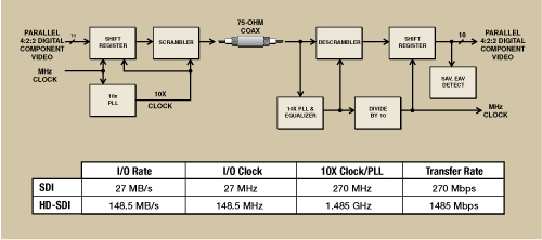
Both the SDI and HD-SDI physical topologies are essentially identical except for operating rate. Figure 4 shows the basic blocks of the transmitter and receiver system. The transmitter receives a parallel stream of 4:2:2 digital component data. A shift register assembles the data into a serial stream. The serial data is clocked through the shift register at 10 times the original rate in order to move 10 bits/sample data. The original parallel-rate sampling clock is multiplied via a phase-locked loop oscillator system to attain the 10X clock rate. The combination of NRZI coding, 10 bits per sample, and data scrambling provided in the last block help minimize DC component on the signal. The scrambled data pattern is governed by a predetermined equation, which is replicated in the receiver to effect successful descrambling.
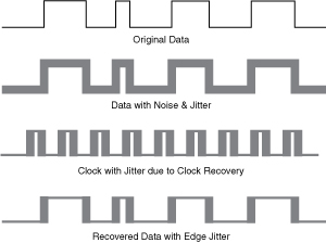
The serial digital signal travels over low-loss coaxial cable to the receiver, which performs the reverse operations of the transmission scheme. The NRZI data coding facilitates recovery of the clock signal directly from within the data stream. A key element of the receiver is its gain structure combined with a cable equalizer. The cable equalizer adjusts itself to account for losses in the cable and adjust gain so that the receiver can slice through data level changes to find the transitions. The presence of jitter impacts detection significantly in that edge transitions appear to move from one point in time to another. The ability to counteract this timing movement is a function of the receiver's phase-locked loop (PLL) performance. The PLL tracks signal transition changes. When this is not possible, synchronization is lost and the HD‑SDI decoding fails. HD‑SDI signal transmission is ultimately limited by three components: signal attenuation, receiver sensitivity, and signal jitter.
The receiver enhances its noise rejection by virtue of its processing topology. Internally, the receiver input resembles a differential amplifier. The signal is first inverted and handled as if it's a balanced signal. Feeding an inverted version of the signal for processing allows the receiver to discern noise from normal signal transitions. Performing the correct adding function eliminates most of the incoming noise.
Cabling and Loss
HD-SDI is regularly transmitted over low-loss digital video grade RG6-style coaxial cable up to a nominal maximum distance of about 100 meters. However, coax is not the only medium available. Serial digital video may be routed through fiber optic cable for essentially unlimited distances depending on the system configuration. The ultimate distance limitation occurs for any digital signal when the perceived signal jitter component seen by the receiver impairs its ability to recognize and reconstruct bit transitions.
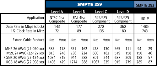
The range of operation for an HD-SDI receiver is specified in SMPTE 292M to at least -20 dB at one-half the data clock rate, or about 743 MHz. Therefore, a standard level 0.800 volt peak-to-peak digital transmission may be attenuated to as low as 0.080 volt, or 80 millivolts, while performing reliably. A very high-grade receiver may recover the HD‑SDI signal at a level as low as -30 dB, or 70 mV.
To perform a cable loss calculation, the designer should look for the attenuation in dB at 743 MHz, or a frequency very close to that value, on the cable specification loss chart. Cable loss is based on a 100 foot length or a 100 meter length depending on the chart column used. Divide the cable run distance by 100 and then multiply by the dB value to attain the total attenuation in dB for that run. Refer to Table 1 containing pre-calculated run lengths for Extron's coaxial cable products. The SMPTE recommends the designer factor in about 10% less cable than the calculated run length so as to build in a safety margin for reliable operation. That 10% is already included within Table 1.
HD-SDI & Associates
SMPTE 292M defines HD-SDI and is based on the constructs of SMPTE 259M, which defines standard definition serial digital. SMPTE 274M defines dimensions for all timing and digital video data description for the HD video formats. Moreover, it addresses image structure, colorimetry, raster structure, digital presentation, timing references, analog sync, and an analog interface.
SMPTE 348M describes a variation of HD-SDI called the high definition serial transport interface. HD‑SDTI is a protocol whereby data other than video/audio may be transported using the HD‑SDI constructs and a portion of the hardware utilized by HD‑SDI. This transport interface is analogous to a freight train pulling a group of rail cars suitable for handling a wide range of goods, not just specific items. The original box car fulfilled this need and, with HDSDTI, a similar methodology allows a designer to load any type of data onto the protocol; providing it can fit within the protocol's basic confines. Utilization of HD‑SDTI for data other than high definition video requires the proper custom formatting and de-formatting hardware for data loading and recovery.
SMPTE 372M standardizes high definition serial digital for full bandwidth transmission; i.e. 4:4:4:4 sampling. Operating at dual-rate (two times the 1.485 Gbps rate) means that twice the information may be transmitted. At nearly 3 Gbps, component video can be accommodated without band-limiting the sample rate for chroma information. The fourth '4' in the sampling structure represents the ability to include an 'alpha' channel along with video data.
Alpha channel describes a data set that can provide special control over image data, such as image masking. For example, an image background may be removed or replaced at the destination utilizing an alpha channel mask originated at the video source. The alpha channel provides detailed information that determines boundaries for information to be maintained or discarded from view.
Another feature of dual rate HD-SDI is the ability to support full RGB formats in the television domain. SMPTE 372M supports a wide variety of component formats and is but one of the stepping stones toward wideband digital cinema recording and support. Multiple feeds of dual-rate HD‑SDI may be combined to escalate image resolution accordingly. Management of cable lengths and data skew then becomes an important issue.
Re-Clocking for More Distance
Another term commonly discussed and specified is "re‑clocking". Re‑clocking the signal is the process of recovering the signal and outputting a reformed version that replicates the original source signal as closely as possible. Re‑clocking also restores the signal to standard level and attempts to minimize jitter. This action is typically used to increase signal distribution distance. Video sources handled by matrix routers are usually reclocked. Re‑clocking methodologies are not all the same from one type of equipment to another.
Re-clocking is normally performed at the input stage of a receiver utilizing a wideband phaselocked loop (PLL) system. The wideband PLL is more capable of following input signal jitter as the receiver "looks" for signal transitions. See Figure 5. Tracking jitter helps control its propagation. However, the receiver itself always imparts some jitter to the signal…this is unavoidable. Since the receiver cannot predict when a transition will occur, its intrinsic delay imparts jitter related to its response time. A receiver having tight control over its response time adds less jitter to the signal.
Got Audio?
No discussion would be complete without addressing audio. While video represents the lion's share of required bandwidth, audio is an important part of the package. Several audio formats may be embedded within the HD‑SDI. SMPTE 292M provides mapping for 24‑bit AES digital audio as well as AES3 digital audio in the 32 to 48 KHz range. The preferred audio data rate is 48 KHz since it is easier to synchronize with the video rate. HD‑SDI supports from two to 16 audio channels. Normally, audio data packets are multiplexed into the chroma signal's auxiliary data space during the blanking interval. However, it may also be multiplexed into the video ANC (ancillary) space as well.
Final Equalization
HD-SDI compares favorably to other digital transports when considering its robustness for high data rate handling capability over hundreds of feet of coaxial cable. With fiber optic transmission technology, run distance is virtually limitless, depending more on cost than technical issues. HD‑SDI-based systems can be customized to handle a host of data. Custom implementations require an appropriate data formatter/deformatter combination.
Concerned about using UTP cable? Be on the lookout for the debut of HD‑SDI over simple UTP cable supporting that magical 100 meter run distance allowed by standard network connections. HD‑SDI will not replace the adrenaline rush of falling off the "data cliff" at that unforgettable moment when image failure occurs, but with even reasonable care, it delivers on simplicity, reliability, and performance.