Multiplexing Signals in Fiber Optic Systems
Time Division Multiplexing
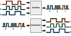
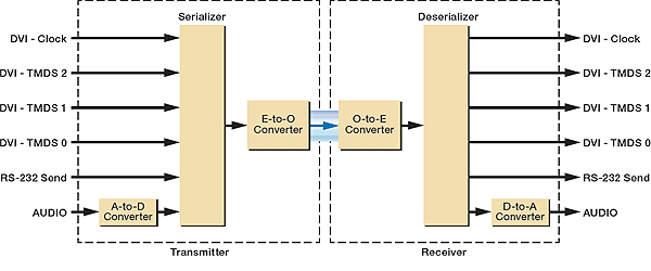
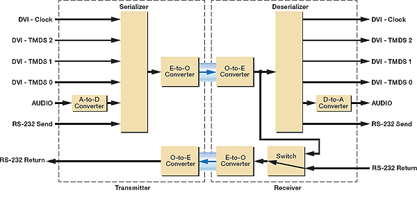
TDM combines multiple digital signals into a single serial digital bit stream. A specialized circuit, called a serializer, allocates parallel input streams into time slots in the serial output. In a fiber optic system, the serial bit stream is transmitted as a single wavelength down a fiber optic cable. On the far end of the channel, a deserializer reconstructs the original parallel signal from the serial bit stream as shown in Figure 1. The serial data rate must be sufficiently fast to ensure no data is lost. Fiber optic transmitters and receivers for high resolution AV signals typically operate at a 4 to 6 Gbps data rate.
TDM is used to transmit a wide variety of signals, including HDMI, DVI, 3G-SDI, RGB, HD and SD component video, S-video, composite, USB, audio, and RS-232 control. In modern fiber optic AV systems, analog video and audio are converted to digital signals, avoiding nonlinear effects that plague direct optical conversion of analog signals. Digital transmission ensures high-resolution video is transmitted pixel-for-pixel along the fiber optic cable.
The transmitter in Figure 2 accepts HDMI/DVI video, stereo audio, and RS-232 control signals. The multiplexer combines the signals as a serial stream of digital pulses. An electrical-to-optical – E-to-O converter changes the digital pulses to light pulses at a single wavelength for transmission down the fiber. The receiver on the far end converts the signal from optical to electrical – O-to-E before deserializing to restore the original signal.
Wavelength Division Multiplexing
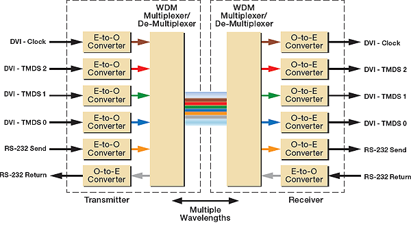
WDM refers to transmitting two or more optical signals at different wavelengths along a single fiber. Multiple wavelengths traveling down a fiber is similar to multiple radio signals traveling through the air at different frequencies. Each wavelength can carry a different signal that is independent of the other wavelengths. Additionally, the different wavelengths can travel in the same or opposite directions, enabling bidirectional optical communication over a single fiber as shown in Figure 3. As long as the optical converters have a sufficiently high bandwidth, WDM enables the original signal format and data rate to be maintained in both the electrical and optical domains.
WDM is suitable for any application where multiple signals are transmitted over fiber optic cabling. The signals can be completely independent, such as for different channels in a cable television environment, bidirectional USB or RS-232 signals, components of a multi-lane HDMI or DVI signal, or a combination of these. Each signal is applied to a different wavelength for independent transmission along the same fiber optic cable.
The WDM transmitter and receiver shown in Figure 3 enable transmission of an HDMI/ DVI signal over fiber optic cable. The transmitter has five inputs and one output. Each inpu has its own E-to-O converter with a laser diode that operates at a unique wavelength. A special device called a WDM multiplexer/de-multiplexer combines the various wavelengths for transmission down a fiber optic cable.
The WDM multiplexer/demultiplexer also separates the optical signal used for the return data, which operates at a wavelength different from the inputs. The return data optical signal passes through an O-to-E converter to recover the original signal.
The WDM receiver shown in Figure 3 has one input and five outputs. The WDM multiplexer/demultiplexer in the receiver separates the optical signals, sending each to a separate O-to-E converter.
Bidirectional Signaling
Bidirectional signals, such as USB, RS-232, or Ethernet, are used in a wide variety of AV applications. As shown previously in Figure 3, a WDM system transmits bidirectional signals over a single fiber using a unique wavelength for the return data. In a TDM system, single wavelength transmission is inherently unidirectional, so bidirectional signaling is accomplished by using a second fiber as shown in Figure 5.
AV Signal Transmission Distance
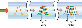
In a WDM system, the maximum transmission distance is affected by optical loss, fiber bandwidth, and inter-channel skew. Optical loss equates to attenuation in the fiber, connections, and splices. The loss budget, determined by transmitter output power and receiver input sensitivity, is the maximum amount of allowable optical loss in the fiber link between the transmitter and receiver. Fiber bandwidth is the maximum frequency or data rate that can be transmitted along a given length of fiber optic cable. Skew is caused by the various wavelengths propagating at different speeds along the fiber as shown in Figure 4. The result is similar to skew created by varying twist ratios in Category cable within a twisted pair system.
The amount of skew in a WDM system depends upon the range of wavelengths used in the system. In multimode systems using wavelengths around 850 nm, skew can be the dominant effect limiting transmission distance. For example, an HDMI system with a 225 MHz pixel clock has a maximum allowable inter-channel cable skew of 1.78 ns.
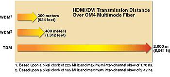
A popular device used in multimode WDM HDMI and DVI extenders has a specified maximum istance around 300 meters (984 feet) before the skew exceeds 1.78 ns. The same device can operate up to 400 meters (1,312 feet) for an HDMI or DVI signal with a 165 MHz pixel clock to allow a maximum skew of 2.42 ns.
A TDM system transmits the fiber optic signal at a single wavelength, such that the entire signal propagates at the same speed. With negligible skew, the maximum transmission distance is limited only by the available loss budget and system bandwidth. A wellmanaged loss budget and use of high-bandwidth, laser-optimized OM4 fiber enables multimode TDM systems to achieve distances up to 2 km (6,561 feet), as shown in Figure 6. As a result, TDM systems achieve much greater transmission distances than WDM systems used for AV signal extension.
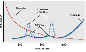
Singlemode systems use long wavelengths around 1310 nm or 1550 nm. At these wavelengths, WDM systems experience less inter-channel skew to achieve longer transmission distances. A typical WDM singlemode system for HDMI/DVI signals transmits up to 12 km (7.5 miles), compared to 30 km (18.75 miles) for a TDM singlemode system. However, not all WDM systems support OS1 fiber, which is the most common type of installed singlemode fiber. WDM systems with wavelengths around 1390 nm suffer high attenuation in OS1 fiber due to water peak absorption as shown in Figure 7.
Attenuation severely limits the transmission distance. Around the 1390 nm wavelength, OS1 fiber attenuation can 4 dB/km or more due to water peak absorption. Assuming a loss budget of 10 to 13 dB, the maximum transmission distance is only 2 to 3 km at this wavelength. In order to achieve longer transmission distance, this type of WDM system requires OS2 low water peak singlemode fiber. Alternatively, a singlemode TDM system uses either a 1310 nm or 1550 nm wavelength, where OS1 fiber attenuation is typically 1 dB/km or less, so it operates at its full distance capability over both OS1 and OS2 fiber types.
Daisy-chaining
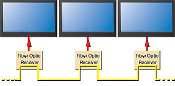
Daisy-chaining allows a signal to be delivered to multiple destinations without the need for routing or distribution equipment, or multiple transmitters as shown in Figure 8. An AV signal from a single transmitter, or from a single output on a matrix switcher, is sent to a receiver with daisy-chain capability. The receiver provides a loop-out signal that is sent to the next receiver in the daisy-chain. This configuration utilizes a single fiber from the transmitter or matrix output to the first receiver in the chain. A single fiber connects each consecutive receiver in the chain for efficient use of the fiber infrastructure. A daisy-chain configuration is ideal for digital signage applications.
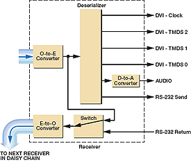
In a TDM system, the second fiber used for bidirectional communications is often available as a loop out for creating a daisy-chain configuration as shown in Figure 9. Since there is a single bit stream, retransmission of the signal requires only a single E-to-O converter. Alternatively, a WDM system is transmitting multiple bit streams, requiring multiple optical converters and an additional WDM multiplexer/demultiplexer to implement a loop-through. Therefore, a WDM receiver typically has only a single fiber connection, and cannot be connected in a daisy-chain configuration.
Secure Systems
Secure environments include any system that deals with sensitive information, such as government and military briefing rooms, emergency operations centers, or a corporate presentation or planning room for proprietary technology. Many of these systems must access information from both secure and public sources. Secure sources are referred to as "red" signals, while public sources are referred to as "black" signals.
The detailed requirements for secure systems are often classified and not available to the public, but general guidelines have been declassified. Secure systems with black sources must take great care to ensure red information does not "leak" out through the connection to the black source. Red and black systems must be electrically isolated from each other. In a copper-based system, red and black signals must remain physically separated. Since fiber optic cables are made of glass, a fiber optic system is preferred as it provides near-perfect electrical isolation between black and red signals, see Figure 10.
Secure systems require that signals from public sources be unidirectional. Transmission of any signal from a "red" secure system to a "black" unsecure system is not permitted. Because of this, TDM fiber optic systems are preferred over WDM systems. Bidirectional fiber optic devices that use WDM techniques are prohibited from use to connect a black source to a red system.

Switching and Distribution
Active Switching and Distribution in AV Systems
Switching systems used in fiber optic AV systems typically employ optical inputelectrical switching-optical output – OEO technology. The optical signal is converted to the electrical domain at the input of the router, switcher, or distribution amplifier.
It is then processed in the electrical domain, and restored to an optical signal at the output. OEO systems restore full transmission power level on the output to preserve the optical loss budget. The use of OEO technology avoids the losses that occur in optical input-optical switching-optical output – OOO systems that use passive splitters to distribute optical signals to multiple destinations, which is particularly important when multicasting a fiber optic AV signal to several displays.
Switching and Routing Fiber Optic TDM AV Signals
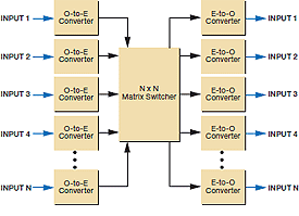
TDM switching systems process a single serial bit stream for each signal to produce an efficient, compact design. The single wavelength/single fiber switching system performs a single E-to-O conversion for each input and a single O-to-E conversion on each output as shown in Figure 11. High-speed digital switching ensures pixel-for-pixel performance for high resolution video signals. The matrix switcher also maintains the serial format of the signal to simplify switching and maintain proper timing.
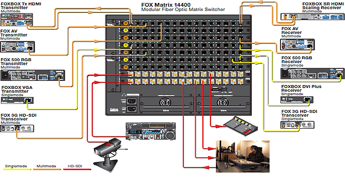
Maintaining the serial digital bit stream enables switching to be independent of the underlying video format as shown in Figure 12. This allows the distribution system to support a wide variety of digital signals, including HDMI/DVI, 3G-SDI, USB, RS-232, and other digital signals. Signal types are defined by the endpoints – the transmitter and receiver. Serial digital signals, such as 3G-SDI, are supported in their native format, enabling local inputs and outputs.
Bidirectional signals are easily handled by using two fibers, an input and output that are switched together. However, multi-lane signals such as HDMI, DVI, and RGB require external transmitters and receivers to provide local inputs and outputs. The ability to support a wide variety of signals simplifies upgrading of sources and displays with minimal impact on the switching and routing system.
The efficient design of a TDM matrix switcher enables a large number of inputs and outputs in a compact space with moderate power requirements. The Extron FOX Matrix 14400 shown in Figure 12 provides a full 144x144 non-blocking fiber optic matrix switcher in an 8U frame.
Switching and Routing Fiber Optic WDM AV Signals
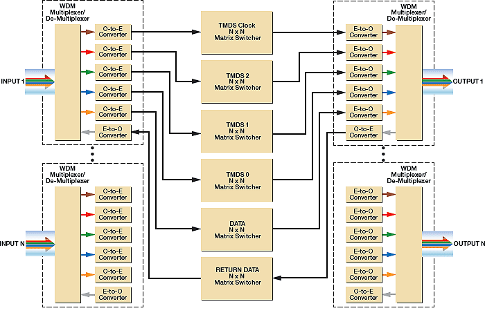
A matrix switcher for WDM signals is larger and more complex than that used for a TDM signal as shown in Figure 13. Each fiber optic input includes the complete WDM receiver circuit to convert the optical signal to an HDMI/DVI format. The core switching system supports the multi-lane format of an HDMI/DVI signal, which requires multiple, parallel internal switching components. Each fiber optic output includes the complete WDM transmitter circuit to convert the HDMI/DVI signal back into an optical signal. The additional switching resources and I/O circuitry causes WDM matrix switchers to be large, high powered, and require additional cooling. Since the core switching system supports HDMI/DVI signals in their native format, local inputs and outputs are easily added to the matrix. Supporting other signal types, such as 3G-SDI, requires external converters to change the original signal into a DVI/HDMI signal. WDM matrix switchers do not typically support local 3G-SDI signals.
Relative Matrix Sizes of TDM and WDM Matrix Switchers
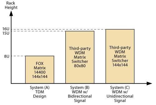
A high speed digital matrix switcher in a TDM system operates efficiently, typically using less power than a WDM matrix switcher. The efficient design also enables a TDM matrix switcher to occupy less rack space. For example, System A in Figure 14 is the Extron FOX Matrix 14400 144x144 fiber optic matrix switcher that occupies eight rack units. It is compatible with the complete family of FOX Series transmitters and receivers to supports HDCP-compliant HDMI, DVI, 3G-SDI, RGB, HD/SD component, S-video, composite video, USB, stereo audio, and RS-232 control signals. A matrix board is also available to provide local 3G-SDI signals.
System B in Figure 14 is an 80x80 WDM matrix switcher that is almost twice th size at 15 rack units, and supports HDCP-compliant HDMI and DVI signals. It lacks support for 3G-SDI signals, standard definition video, audio, USB, and control, but does provide local HDMI and DVI inputs and outputs. System C in Figure 14 is a 144x144 WDM matrix switcher that consumes 16 rack units, but only supports non-HDCP DVI, VGA, HD component video, audio, and one-way RS-232 control. It lacks support for 3G-SDI signals, standard definition video, and bidirectional RS-232. As a WDM matrix switcher, it does support local DVI or VGA inputs and outputs, but not HDCPcompliant HDMI. The TDM system is the most compact design with complete support for AV signal types. Support for local 3G-SDI signals can be provided within the modular matrix frame. Local inputs and outputs for other signal types are provided with the compact transmitters and receivers. WDM systems require significantly more rack space for the matrix switcher and support fewer signal types. For example, System B in Figure 14 would consume 30 rack space units in order to provide the same switching resources as in the FOX Matrix 14400. The FOX Matrix consumes significantly less rack space, even with the addition of a few transmitters and receivers for local HDMI inputs and outputs.
Summary
Both TDM and WDM are common technologies implemented in fiber optic AV systems. Each has its own unique advantages and challenges. The table below compares and contrasts the two technologies:
| TDM | WDM | |
|---|---|---|
| Up to 2 km on multimode fiber | 300 to 400 m typical | |
| Up to 30 km on singlemode fiber | Up to 12 km on OS2 fiber. OS1 depends on wavelengths |
|
| Bidirectional signaling | ||
| Extend HDMI / DVI Signals | ||
| Extend RGB Signals | ||
| Extend 3G-SDI signals | Requires Conversion | |
| HDCP Support | ||
| USB Extension | ||
| Daisy Chain Capability | w/ loop-through | Not typically supported |
| Preferred for secure systems | ||
| Low power matrix switcher | ||
| High I/O density matrix switcher | ||
| HDMI / DVI Local I/O | w/ external converters | |
| RGB Local I/O | w/ external converters | Digital-to-analog conversion |
| 3G-SDI Local I/O |